Руководство по разгону процессора Core i9-10900K на материнских платах ASUS ROG Maximus XII
Данная статья является вольным переводом информационного сообщения пользователя Falkentyne на Overclock.net.
Некоторые термины оставлены без перевода, чтобы вам было проще найти эти параметры или значения в меню BIOS Setup. Если вы нашли неточность в переводе, то можете обратиться к редактору GreenTech_Reviews через электронную почту ([email protected]).
Автор оригинального сообщения, автор перевода и редакция GreenTech_Reviews не несут ответственности за вышедшие из строя комплектующие в результате установки неверных параметров. Данный материал несёт ознакомительный характер. Все действия вы производите на свой страх и риск.
———————————————————————————————————————-
Данная статья является набором рекомендаций по разгону K-процессоров на материнских платах ASUS ROG серии Maximus XII (12).
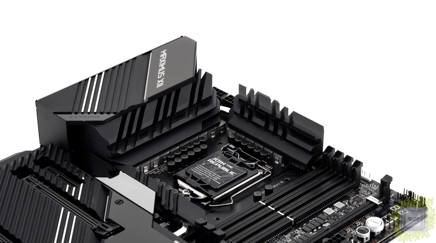
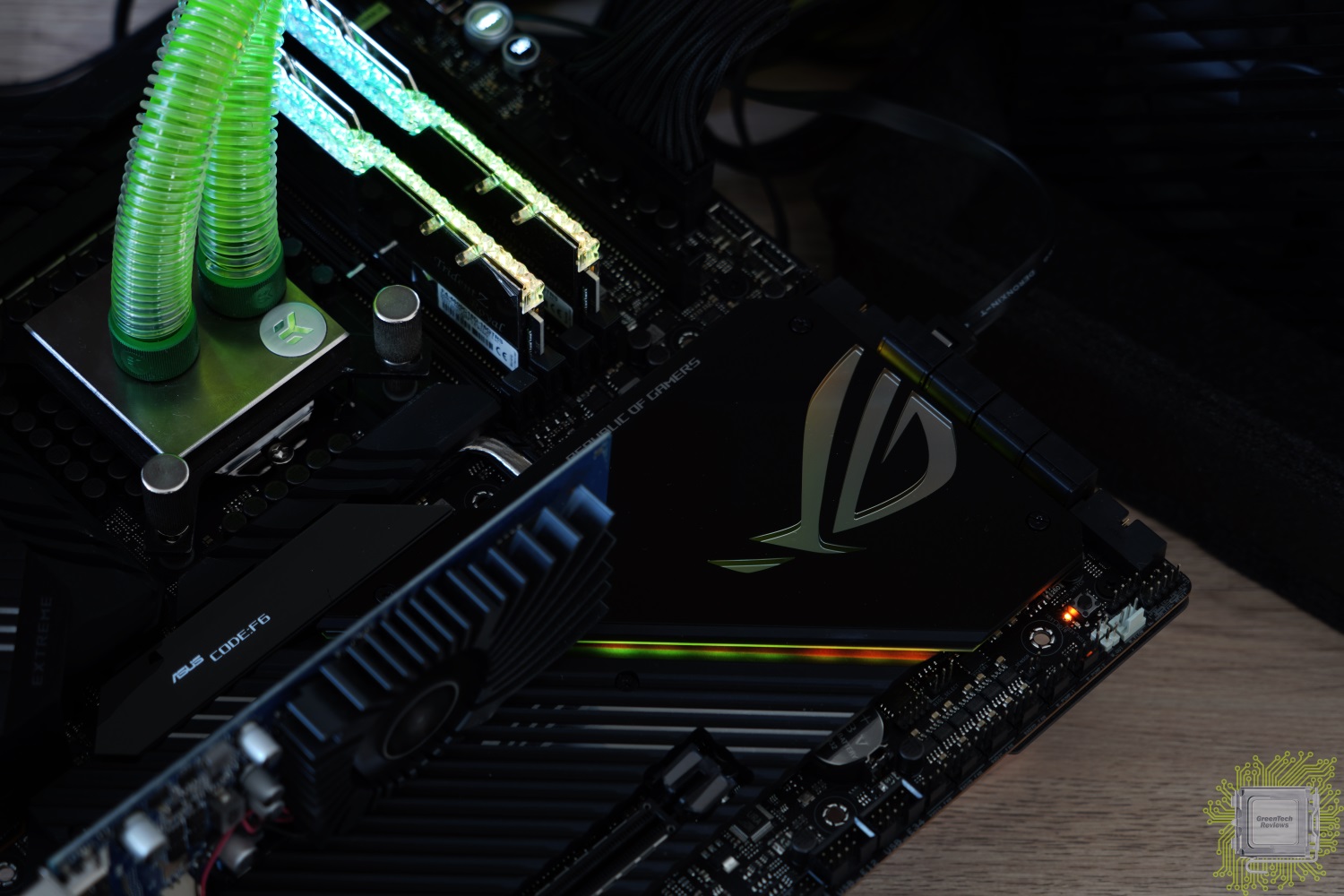
Для подготовки статьи была взята материнская плата Maximus XII Extreme, но рекомендации подойдут и при использовании других плат серии..
Речь в данной статье пойдёт о разгоне процессора Core i9-10900K.
Версия BIOS на момент подготовки статьи: 0508.
Автор выражает огромную благодарность Shamino за предоставленный тестовый стенд и рекомендации по его настройке.
Простой путь для тех пользователей, кто хочет просто играть в игры или приступить к иной работе.
Используйте полностью автоматический режим (Load optimized defaults в BIOS Setup), чтобы система работала в полном соответствии с рекомендациями Intel для конкретного процессора.
Вы можете проверить значение «SP» или «качество процессора» в BIOS.
В среднем у большинства пользователей это значение составляет 63.
Мировой рекорд по разгону под жидким азотом установлен на чипе с рейтингом 117.
Загрузите операционную систему и запустите простой тест нагрузки, например — Cinebench R20.
Затем вернитесь в настройки BIOS и установите параметр Core Ratio в режим AI Optimized.
Подсказка: точные настройки режима AI Optimized для вашего процессора вы можете найти в разделе «AI Features».
Также вы можете активировать профиль XMP для вашей оперативной памяти.
Но сегодня речь пойдёт не о разгоне оперативной памяти, а только о разгоне процессора.
Включите профиль XMP оперативной памяти и установите множитель частоты процессора. Больше ничего делать не нужно.
При частоте процессора от 4.8 до 5.1 ГГц никакие другие параметры менять не придётся, система будет работать в автоматическом режиме.
Для игр можно установить частоту 5.0 ГГц для всех ядер.
Недорогой кулер (воздух): 4.8 ГГц
Дорогой высокоэффективный кулер (воздух): 4.9-5 ГГц
Хорошая необслуживаемая (AIO) система жидкостного охлаждения: 5-5.2 ГГц, но зависит от «качества» процессора
Система жидкостного охлаждения из премиальных компонентов, чиллер, скальпирование: 5.2 ГГц без проблем, далее зависит от «качества» процессора
Экстремальные стресс-тесты: 4.8 ГГц «на воздухе», 5 ГГц «под водой».
Если оставить все настройки по умолчанию, то процессор будет использовать функцию Thermal Velocity Boost (только для i9-10900, i9-10900K/F/KF), которая является частью технологии Turbo Boost 3.0 (только для всех моделей i9-10900 и i7-10700).
Технология позволяет получить 4.9 ГГц по всем ядрам, если температура процессора составляет менее 70°C. Иначе частота составит 4.8 ГГц (технология Turbo Boost 2.0). При лёгких нагрузках два лучших ядра будут работать на частоте 5.3 ГГц, если температура процессора составляет менее 70°C. Иначе — 5.1 ГГц..
1) Только два лучших ядра могут достигать множителя x53. Вы можете узнать какие именно это ядра в BIOS в разделе «CPU Configuration» или в самой новой версии утилиты CPU-Z по кнопке Tools и там Clocks (выделены красным цветом).
2) Windows 10 версии 1909 или новее требуется для работы этой технологии.
3) Вы можете получить множители x53 при лёгких нагрузках при помощи технологии TB 3.0 если:
a) загружено не более 2 ядер;
b) эти 2 ядра отмечены как «лучшие» системой.
Помните, что при автоматических настройках будут соблюдены ограничения по энергопотреблению (Power Limit) и времени увеличенного энергопотребления (Tau) в соответствии со спецификацией Intel. Максимальное по умолчанию значение 250 Вт — «краткосрочное» значение «Power Limit 2», далее система ограничит процессор значением 125 Вт — «долгосрочное» значение «Power Limit 1».
Установка всех параметров вручную приведёт к достижению максимальной производительности и полному отключению ограничений (Power Limit 1 и 2), а также отключению ограничений технологии Thermal Velocity Boost.
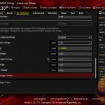
Хотите полностью взять на себя контроль за напряжением процессора без риска выйти за пределы безопасных значений? Это просто.
BIOS автоматически протестирует вашу систему охлаждения. Вы можете загрузить операционную систему, поработать в привычных программах, а затем перезагрузить систему и BIOS произведёт дополнительную калибровку системы охлаждения.
И тогда можете посмотреть полученные значения. Для большинства пользователей важно значение напряжения в режиме «Non AVX». Именно это напряжение надо считать максимально допустимым для установки в BIOS. Также следует установить значение «Level 4» для параметра «Loadline Calibration». Вручную установите значение, близкое к тому, что предложила система с шагом на 0.5 мВ выше. К примеру, если прогнозируемое напряжение составляет 1.172 В, то установите 1.175 В, а не 1.170 В.
Это всё, что от вас требуется. В таком режиме система будет стабильно работать в 99% приложениях, включая обычные стресс-тесты и стресс-тесты с реалистичным использованием AVX инструкций (Realbench 2.56, Cinebench R20, Prime95 AVX disabled small FFT, AIDA64 Stress FPU).
Стресс-тесты Prime95 small FFT с AVX или FMA3, Y-cruncher AVX2, LinX 0.9.6, Linpack Extreme не важны для 99% пользователей! Давайте проявим здравомыслие и не будем считать это важным. Но если, всё же, для вас это важно, то давайте поговорим и на эту тему.
BIOS материнских плат ASUS считается самым продвинутым и самым удобным для настройки системы.
По сравнению с платформой Z390, напряжения требуются ниже. Более не требуется 1.35 В IO/SA для запуска профиля XMP с частотой оперативной памяти 3200 МГц. Все автоматические настройки (BIOS Defaults) теперь на 100% ограничены по всем лимитам и напряжениям в соответствии со спецификацией Intel. Правда, некоторые материнские платы конкурентов нарушают эти правила, как это было и в случае с платами Z390.
Самая главная функция плат ASUS – богатый набор настроек напряжения.
Мной был тщательно протестирован процессор Core i9-10900K на частотах 4.8-5 ГГц для всех ядер, после чего я могу с уверенностью сказать, что установки напряжений на плате ASUS буквально на 100% соответствуют действительности.
Платы ASUS характерны наличием двух вариантов: Non AVX и AVX. Оба варианта характерны значением «Level 4» для параметра «Loadline Calibration». Результаты калибровок становятся менее точными при более высоких значениях уровней из-за увеличений скачков напряжений. В частности, это хорошо заметно при значении «Level 6», поэтому, если вы планируете установку такого уровня, вам придётся подбирать параметры вручную. Я использую Level 4 при 5.2 ГГц для всех ядер в Cinebench R20.
Пример того, как себя ведёт напряжение при разных уровнях LLC можно посмотреть по ссылке, где для изыскания была взята материнская плата ASUS ROG Maximus XI Gene: https://elmorlabs.com/index.php/2019-09-05/vrm-load-line-visualized/
По сообщениям пользователя с псевдонимом Buildzoid именно абсолютное минимальное значение напряжения определяет стабильность, а не среднее.
Благодаря оптимизации подсистемы питания плат ASUS на базе чипсета Z490, значение «Level 4» позволяет добиться минимального провала напряжения.
Немного о работе LLC
Данный параметр обычно задаётся в мОм (миллиом) и определяет, насколько уменьшается выходное напряжение при нагрузке. В соответствии с законом Ома U = R*I. Падение напряжения вычисляется как Load—Line*I(out) (выходной ток). К примеру, для Load—Line 1 мОм и тока 100 А будет справедлив расчёт dU = 0.001 Ω * 100 A = 0.100 В. То есть, при напряжении 1.300 В и нагрузке 100 А реальное выходное напряжение будет 1.300-0.100 = 1.200 В. Основная причина использование Load—Line заключается в минимизации скачков (завышений) напряжения при переходе от высокого к низкому выходному току и достижения более предсказуемого поведения.
Подбирать минимально стабильное напряжение (с учётом вашей системы охлаждения) надо при использовании не-AVX стресс-теста, основанного на программе Prime95 29.8 build 6 small FFT без использования AVX. Обычным пользователям стоит сфокусироваться на таком подходе, так как его вполне достаточно.
При полной нагрузке это будет называться vMin – минимальное напряжение, необходимое для обработки инструкций SSE2 без ошибок. Если при полной нагрузке в иных приложениях напряжение упадёт ниже vMin, чем мы подобрали для Prime95, то со стабильностью в этих приложениях могут возникнуть проблемы.
Обратите внимание, что инструкции AVX являются расширением SSE2, поэтому полностью стабильная работа SSE2 для нас очень важна. Да, при использовании инструкций AVX используется большее потребление тока и выделяется больше тепла, но, вопреки заблуждению многих пользователей, значение vMin при выполнении таких инструкций практически не отличается. Но что меняет минимальный уровень – это тепло. Vdroop не меняет минимальный уровень напряжения, а только изменяет начальное напряжение, необходимое для компенсации.
В моих тестах (при условии правильно выставленных напряжениях VCCIO и VCCSA) при настройках в BIOS для не-AVX тестов система для рядовых пользователей работает полностью стабильно в не-AVX приложениях и даже при реалистичном использовании AVX инструкций — Realbench 2.56, Cinebench R20, AIDA64 «Stress FPU», and Battlefield 5.
Я обнаружил, что стресс-тест Prime95 small FFT с отключённым AVX, Realbench 2.56, CB R20 и AIDA64 «Stress FPU» очень похожи в нагрузке и требуют практически идентичного напряжения в целом.
Значение «Die sense» на платах ASUS чрезвычайно близко к реальности и при нагрузке Prime95 small FFT без AVX является для нас целевым значением. Если при нагрузке с AVX этот показатель остаётся аналогичным или выше Vmin, то система должна быть полностью стабильной. Но чего стоит опасаться, так это того, что Vmin будет ниже в полных AVX нагрузках – тогда будут возникать проблемы со стабильностью.
Установка напряжения в BIOS для AVX задач основана на кратком тесте Prime95 small FFT с AVX.
Я обнаружил, что это напряжение предсказывается не так точно, как в случае предсказания для нагрузок без AVX даже на уровне «Level 4», потому что напряжение в «Die sense» для использующих AVX программ может падать ниже предсказанного значения Vmin в Prime95 small FFT без AVX. Это может привести к нестабильной работе системы, поэтому вам потребуется увеличить напряжение, чтобы оно превышало то, что вы видите в нагрузке в тесте Prime95 small FFT без AVX. Вы можете смотреть показатель WHEA в программе HWinfo64, чтобы проверять наличие ошибок CPU Cache L0.
Также имейте в виду, что нагрев процессора будет заметно выше при использовании инструкций AVX, чем без них, поэтому вам потребуется использование более высокого значения Vmin. К примеру, если процессор стабилен в тесте Prime95 small FFT без AVX на частоте 4.7 ГГц при напряжении 1.05 В, то он не будет стабилен в тесте Prime95 small FFT с AVX при тех же параметрах, а также будет горячее на 10-15°С. Вам потребуется компенсировать это улучшением системы охлаждения и увеличением значения Vmin.
Игрокам и пользователям, работающим в профессиональном программном обеспечении, будет достаточно руководствоваться значениями предсказаний Non-AVX в BIOS.
Скажу более конкретно — Prime95 small FFT с AVX не важен для этой платформы. Предсказаний Non-AVX вполне достаточно для повседневного использования большинства обычных AVX приложений.
Если вы не занимаетесь работой в медицинской или научной области, где требуются постоянные расчёты с использованием AVX инструкций, то не беспокойтесь за стабильность работы стресс-теста Prime95 AVX small FFT. Прохождение тестов Prime95 AVX small FFT, FMA3 small FFT, LinX 0.9.6 с объёмом задачи 35000 или Linpack Extreme 1.1 «даст» на ваш процессор ток 250 А – это, конечно, круто и вы будете чувствовать полную уверенность в своей системе, но реально – это не важно! Тепловыделение 10 ядер, сильные изменения Vdroop, огромное энергопотребление – это не симуляции реальных задач для данной платформы. Поэтому не надо слушать тех, кто говорит, что «если у тебя система проходит тест не-AVX small FFT, то она всё равно работает нестабильно». Особенно, если частота процессора составляет 4.8 ГГц и выше.
Кое-что ещё: перестаньте беспокоиться за температуру подсистемы питания. Конечно, всегда приятно видеть невысокие температуры, но подсистемы питания спроектированы для работы при достаточно высоких температурах. Подсистема питания – это не процессор. Подсистема питания не будет внезапно начинать сложные математические вычисления или заставлять «проседать» 12 В линию блока питания до 10 В при 85°С. Температуры 60-70 градусов – это совершенно нормально. Вы всегда можете установить дополнительный вентилятор, чтобы снизить температуру питания. Конденсаторы прекрасно работают при температуре 85°С. А силовые элементы без сбоев могут работать и при температуре 100°С. Поэтому нет смысла говорить, что плата X лучше платы Y, потому что у неё температура 55°С, а не 75°С. Это никак не влияет на производительность.
Теперь о моих результатах тестирования. Это всё мои изыскания, демонстрирующие работу системы с предсказанием значения Non—AVX и LLC4 (Level 4).
Vmin — фиксированное напряжение Vcore, частота 4.7 ГГц.
Установка в BIOS напряжения 1.150 В, LLC4: стабильно в Apex Legends, Minecraft, AIDA64 «Stress FPU» (1.039v в нагрузке! AIDA FPU), Prime95 без AVX тест small FFT.
Vmin: установка в BIOS напряжения 1.145 В, 1.012 при нагрузке: 4 часа стабильной работы Realbench 2.56 при температуре не выше 62°С; AIDA64 в течение часа при напряжении в нагрузке 1.012 В и температуре до 64°С; Prime95 small FFT без AVX (в нагрузке напряжение 1.012 В).
Значение 1000 кГц для «VRM Switching Frequency» делает систему в Minecraft более стабильной, так как Minecraft – это особый случай, при котором игра даёт 100% нагрузку всем ядрам в момент загрузки. Это также разоблачает «ошибку» Internal Parity Error процессорных ядер Skylake, если значение Vmin оказывается выше ожидаемого. Эта ошибка была найдена программистом Oriostorm из студии Respawn при тестировании и отладки игры Apex Legends. Этот «баг» вызывает контроля чётности «Parity Error», а не более ожидаемую ошибку «L0 cache error» из-за низкого напряжения Vcore.
4.8 ГГц, 1.215 В, LLC «Level 4»: AIDA64 stress FPU работает стабильно (1.066 В в нагрузке — AIDA64 FPU стабильно), загрузка Minecraft стабильна, Prime 95 с AVX работает стабильно.
Установленные настройки в BIOS: 1.180 В, LLC4 (Level 4): в AIDA64 Stress FPU 1.048 В, температура 68°С; Realbench 2.56 – 66°С при напряжении в нагрузке 1.048 В, Minecraft Java – случайные ошибки «Internal Parity Errors» во время загрузки.
Minecraft Java Vmin: 1.190 В L4, в реальности в нагрузке 1.066 В, температура 60°C максимум, 22 цикла загрузки, ошибок «Internal Parity Errors» не выявлено.
Абсолютное предсказание Vmin в BIOS: 1.175 В. Установка VRM 1000 кГц, вроде, улучшает стабильность в Minecraft.
4.9 ГГц, 1.225 В, LLC4: загрузка Minecraft Java, AIDA64 (1.083 В в нагрузке в AIDA64 FPU, 145 А, 72°С, 1 час тестирования) с охлаждением Arctic Freezer II 360 (температура в помещении 23-24 градуса).
5 ГГц (4.7 ГГц Cache), 1000 кГц
Тест с LLC4: 1.285 В Vmin SSE3, Normal AVX тесты, загрузка Minecraft, Prime95 SSE2 и т.д. – в нагрузке 1.128 В.
Загрузка Minecraft Java 40 циклов при LLC6, 500 кГц в качестве проверки 100% стабильности работы и наличие ошибок «CPU Internal Parity Error».
Более высокие значения LLC: 1.235 В, LLC6, VCCIO: 1.05 В, VCCSA 1.10 В. В нагрузке Vmin: 1.153 В.
Кое-что ещё
Технология Hyper-Threading очень чувствительна к напряжениям IO/SA, поэтому нестабильность в работе может проявляться при очень близких значениях напряжения к напряжению Vmin. Для проверки как L3 cache/IMC (через VCCIO/VCCSA) может снижать стабильность, используйте Prime95 без AVX с тестом FFT 112k-112k и наблюдайте в HWinfo64 значение количества ошибок WHEA CPU Cache L0, если значение напряжения находится в пределах 10 мВ от вашего напряжения Vmin. Также будет проявляться нестабильная работа во время прохождения 112k теста. Тест 112k – особый случай, так как он фактически попадает в оперативную память и кешируется в ней, что позволяет определить нестабильную работу IMC (контроллера памяти, встроенного в процессор).
При тестировании вашего значения Vmin, если вы установите недостаточные напряжения VCCIO/VCCSA, вы можете получить следующие ошибки:
1) Ошибки «WHEA CPU Cache L0» в программе HWinfo64.
2) System Service Exception (or IRQL) BSOD.
3) Случайные вылеты/ошибки в Prime95.
4) Видео драйвер может быть остановлен во время тестирования.
Небольшой диапазон 10-20 мВ для завышения или занижения IO/SA может вызвать нестабильную работу в 112K-112K тестах Prime95 (без AVX), Realbench 2.56 или AIDA64 Stress FPU, если не увеличить напряжение Vcore.
Если значения для IO/SA установлены правильно, а напряжение Vmin недостаточное, то тест AIDA64 Stress FPU будет сообщать о нестабильной работе вместо BSOD или «падения» видео драйвера.
Я обнаружил, что напряжения 1.05 В для VCCIO и 1.10 В для VCCSA подходят для моей системы. Ваши значения могут отличаться в зависимости от скорости памяти и её таймингов.
Если добиться стабильности не удаётся, то попробуйте увеличить напряжение на процессор. Обратите внимание, что высокоскоростные профили (XMP) памяти требуют более высоких напряжений на IO/SA. Это является причиной требования более высокого напряжения Vcore при разгоне оперативной памяти. Иногда увеличение напряжений IO/SA при памяти с частотой 4000 МГц может позволить немного снизить напряжением Vcore.
Некоторые серьёзные AVX тесты (не зацикливайтесь на small FFT AVX тестах).
Prime95 AVX1 15K: 1.250 В LLC6, VCCIO: 1.05 В, VCCSA: 1.10 В (минимальное зафиксированное напряжение в нагрузке 1.128 В).
Prime95 AVX2 (FMA3) 15K: 1.270 В LLC6, VCCIO: 1.05 В, VCCSA: 1.10 В (минимальное зафиксированное напряжение в нагрузке 1.137 В)
5.1 ГГц: Prime95 AVX1: 1.320 В LLC6 – 100°C (FMA3 невозможно протестировать из-за высоких температур).
5.2 ГГц: Cinebench и игры: 1.380 В LLC4 (предсказание BIOS) — 1.199 В в нагрузке – пройден тест CB R20. В таком режиме я сделал мало проверок. 1.350 В и LLC6 также работает корректно.
5.3 ГГц: загрузка Minecraft, игра в Battlefield 5 полностью стабильны при 1.380 В и LLC7, но стресс-тесты невозможны из-за температур. К примеру, в Battlefield 5 достигается 80°С.
Я использовал высокие значения LLC, так как для частоты 5.3 ГГц предсказаний не было (проверил на нескольких образцах) и Vdroop был слишком высокий, поэтому я хотел получить более низкое напряжение в BIOS за счёт не самого лучшего (высокого) уровня LLC.
Проблема с offset voltage/adaptive при использовании высоких значений AC Loadline и почему 0.01 мОм для ACLL/DCLL – хорошо.
Немного технических бессвязных мыслей.
5.3 ГГц + Offset voltage +5 мВ + SVID Behavior:
Стандартное значение (AC/DC Loadline=0.6 мОм) + Loadline Calibration (по умолчанию Intel — 1.1 мОм = LLC3): как оказалось, это очень ненадёжная связка и непредсказуемое поведение системы в зависимости от теста. Порой в простое напряжение достигало 1.420 В, но случайные ошибки возникали. Но поведение напряжения Vcore было предсказуемым и контролируемым. К примеру, в Cinebench R20 в нагрузке напряжение составляло 1.320 В и не колебалось вверх/вниз. Но при нагрузке в Minecraft или Battlefield 5 напряжение колебалось в огромных рамках – от 1.305 В до 1.480 В, что делало значение Vmin случайным и слишком маленьким. Аналогичная проблема у меня была с платформой Z390, когда я пытался использовать AC Loadline для контроля напряжения при сильном разгоне. Похоже, что ACLL может повысить выходное напряжение в соответствии с формулой:
Vcore=vCPU + (ACLL * IOUT) — (LLC * IOUT) + vOffset
Но похоже, что при смешанных нагрузках не-AVX/AVX при загрузке не всех ядер, ACLL не поднимает напряжение в нужное время, что вызывает увеличение Vdroop, а в других случаях поднимает напряжение во время низкой нагрузки, слишком сильно увеличивая Vcore. Это не ошибка BIOS, а вопрос смешанной нагрузки с сильными импульсными помехами и реакцией AC Loadline на это – я столкнулся с этим на Z390 Aorus Master, когда пытался использовать Offset mode (Auto mode=offset + 0 мВ) с AC Loadline 1.6 мОм, LLC: Standard (1.6 мОм – по спецификации Intel) на 5.2 ГГц. К примеру, 1.32 В в тесте Cinebench R20 всё в порядке, но в Battlefield 5 от 1.28 В (возникали BSOD) до 1.46 В.
Единственный способ избежать этой проблемы – установить ACLL в значение 0.01 мОм, чтобы ограничить возможность увеличения выходного напряжения. Но в таком случае нам потребуется использовать более высокий уровень LLC. Помните: в offset mode чем ВЫШЕ уровень AC Loadline, тем НИЖЕ уровень Loadline calibration нужно устанавливать (ниже уровни LLC = более высокие сопротивления в мОм), поэтому вам нужно держать значения ACLL близко к значениям LLC (VRM Loadline).
Но если вы планируете использовать offset mode с ACLL 0.01 мОм, вам всё равно лучше использовать фиксированное значение Vcore или режим Adaptive Voltage. Единственным преимуществом offset mode с ACLL 0.01 мОм по сравнению с фиксированным напряжением (допустим, вы используется LLC Level 6 в обоих случаях) является возможность снижения напряжения во время простоя системы. Хотя, есть ещё одно преимущество — offset mode с ACLL 0.01 мОм позволит вам использовать технологию Thermal Velocity Boost для для увеличения Vcpu при увеличении температуры, но если вам потребуется использовать более высокие значения Loadline calibration, то результат будет хуже, чем с более высоким значением LLC.
Наличие новой функции настройки кривых V/F может помочь с нестабильностью работы при низких нагрузках при использовании C-States в offset или adaptive режимах. При использовании фиксированных смещений они применяются ко всем точкам напряжения для каждого шага частоты. Вы можете настроить кривую V/F по вашему усмотрению.
Все напряжения установлены автоматически в соответствии со спецификацией Intel. В тесте 3DMark Fire Strike – все ядра работали на частоте 4.9 ГГц. Лично я не заметил применение технологии TVB как игрок даже с учётом хорошей системы охлаждения. Если у вас средняя система охлаждения, то эта технология может быть полезна, но настройка напряжений от ASUS работает настолько хорошо, что вы можете без проблем использовать эти рекомендации (предсказания). Я никогда не видел частоту 5.3 ГГц в играх. Только в обычной работе в Windows. Может быть, кто-то захочет проверить систему в Super Pi или установит приоритет использования ядер в Prime95 или в играх на 1 ядро, то публикуйте свои результаты исследований.
«Избранные» ядра – это два лучших процессорных ядра, которые получат максимальные множители частоты в соответствии с технологией TVB. Вы можете изменить эти ядра в BIOS (в расширенных настройках) и установить желаемые множители в режиме By Per Core Loading. Пользы от этого я не нашёл, но, возможно, это будет полезно для вас, если вы пытаетесь добиться частоты 5.3 ГГц при ограниченных нагрузках.
Теперь вы можете конфигурировать значения смещения напряжения, используемые в режимах Adaptive / Offset Vcore, когда ваш процессор автоматически снижает частоту – то есть в сочетании с использованием технологий C-States, Speedstep и других. Это может помочь избежать проблем «холостого» BSOD, как это было на платформах Z390, когда вы хотели занизить напряжение, но оно менялось ко всему диапазону частот – от 800 МГц до 5 ГГц. При частотах ниже 2 ГГц такое возникает достаточно часто. Я не использую C-States (держу их отключёнными), но некоторым людям их работа нравится больше.
Точки V/F вы можете менять для 800 МГц, 2.5 ГГц, 3.5 ГГц, 4.3 ГГц, 4.8 ГГц, 5.1 ГГц, 5..2 ГГц и 5.3 ГГц.
Shamino вложил в работу над этой функцией много сил, поэтому я не верю, что многие OEM производители будут использовать это. Но если в вашем BIOS такая функция есть – используйте её.
Чтобы использовать режим Adaptive Voltage вам просто необходимо знать ваше напряжение Vmin при используемом вами LLC. Вы можете посмотреть значение Vmin из строки предсказания в BIOS. После того, как вы нашли это значение и проверили систему на стабильность, вам нужно установить смещение так, чтобы напряжение с его учётом было всегда выше значения Vmin. Также вы можете обнаружить, что значение +0 мВ может продемонстрировать идентичный результат во время нагрузки, как и если бы напряжение было зафиксированным и сниженным для времени простоя системы.
Одним из преимуществ режима Adaptive Voltage является возможность снижения напряжения (даунвольтинга) в момент снижения процессором тактовой частоты в простое, если вы хотите использовать план энергосбережения во время простоя.
Дополнительное «turbo» напряжение позволит вам установить необходимое напряжение в режиме «P0», но это значение не может быть ниже, чем заявленный VID. Дополнительное «turbo» напряжение отличается от такового «Offset» в режиме «Adaptive» тем, что первое применимо только к частоте процессора в режиме «P0» (автоматический режим с использованием технологии TVB с множителем х53 для двух лучших ядер). Поэтому, если у вас система работает в лёгкой нагрузке, то вы можете установить множитель х55 для двух лучших ядер и дополнительное «turbo» напряжение, к примеру, 1.5 В. Это высокое напряжение, но озвучено оно только в качестве примера.
Смещение напряжений «Offset Voltage» применяется ко всему диапазону напряжений. Так +50 мВ смещение, к примеру, будет применено ко всем основным ступеням частот будь то 800 МГц или 5.2 ГГц. Вы можете редактировать значения V/F, чтобы установить более высокие смещения для более высоких тактовых частот. Очевидно, что есть достаточно точек ниже 5.1 ГГц и они нам не особо важны, так как нам наиболее интересными являются частоты свыше 5 ГГц. Таким образом построена и таблица, где небольшие шаги это 4.8, 5.1, 5.2 и 5.3 ГГц, а большие шаги допускаются при частотах ниже 4.8 ГГц.
AC Loadline помогает установить рабочее напряжение процессора, основанное на качестве процессора и его регулировки по току. Вы можете думать об этом как о Loadline Calibration со стороны процессора, а не на стороне подсистемы питания (Vdroop). Эта разработанная Intel спецификация проста в реализации, но не всегда даёт нам то, что необходимо и может из-за этого вызывать проблемы, если вы используете высокое значение ACLL в режимах Auto/Offset для Vcore.
Подсказка: в режимах Vcore Auto/Offset чем выше значение AC Loadline (CPU Input voltage) в мОм, тем выше должно быть значение Loadline Calibration в мОм (ниже уровень LLC или больше Vdroop). Никогда не комбинируйте высокие значения ACLL (мОм) с низкими значениями Loadline Calibration (мОм)!
CPU Vcore (мВ)= vCPU + (ACLL * IOUT) — (LLC * IOUT) + vOffset
Где: vCPU = базовый VID процессора в мВ (с учётом ACLL, DCLL=0.01 мОм + напряжение Thermal Velocity Boost в зависимости от температуры),
ACLL = AC Loadline в мОм
DCLL = DC Loadline в мОм
LLC = VRM Loadline (Loadline calibration) в мОм
iOUT = ток CPU в А
vOffset = напряжение смещения в мВ
Thermal Velocity Boost увеличивает vCPU в зависимости от температуры, так как при увеличении температуры процессору требуется увеличение напряжения. Я считаю, что каждые -2.5 мВ позволяют снизить температуру на 1°С, начиная от 100°С и каждые +2.5мВ увеличивают температуру на 1°С начиная с 0°С.
Для более детальных значений вы должны конкретно понимать связь между VID и Vcore.
CPU VID на самом деле vCPU + (ACLL * dI) — (DCLL * I) + vOffset
Я не знаю что означает dI. Эту формулу я получил от Elmor, но dI=d1-d0. Но приведённая выше формула объясняет наличие и использование DC Loadline равной VRM (LLC) Loadline в мОм.
Поэтому имеет смысл фраза, что AC Loadline управляет рабочим напряжением, при котором процессор пытается сохранить ACLL на уровне vCPU, если DC Loadline = VRM Loadline (LLC и DCLL также в мОм).
Это отлично работает при сбалансированной нагрузке в виде Prime95 или Cinebench.
Давайте возьмём в пример ток 100 А.
vCPU=1.215 В (1215 мВ) @ 5 ГГц
Температура 30°C (vCPU будет ниже, если температура процессора будет ниже и наоборот – это зависит от технологии TVB).
Ток 200 А в полной нагрузке в Cinebench R20.
Loadlines – безопасные значения от Intel. AC Loadline: 1.1 мОм, DC Loadline: 1.1 мОм. Loadline Calibration: level 3 (1.1 мОм). Помните, что DCLL используется только для измерения мощности (CPU VID/CPU package Power as CPU Package Power=VID * IOUT).
Loadlines: Intel’s fail safe: AC Loadline: 1.1 mOhms, DC Loadline: 1.1 mOhms. Loadline Calibration: level 3 (1.1 мОм). Remember DCLL is used only for power measurements (CPU VID/CPU package Power как CPU Package Power=VID * IOUT).
Мы можем использовать режим Vcore offset +005 В (близко к 0 мВ) или режим Adaptive +0 мВ.
Температура в нагрузке – 70°C. Нужно немного расчётов.
Увеличение температуры 70°C-30°C=40°C. 40 * 2.5 мВ = 100 мВ. (Thermal Velocity boost)
Итак vCPU = 1215 мВ + 100 мВ = 1315 мВ.
Vcore: 1315 мВ + (1.1 * 200) — (1.1 * 200) + 0
1315 + (220 мВ) — (220 мВ) =1.315 В напряжение в нагрузке.
В этом примере напряжение в тесте Cinebench должно быть около 1.315 В. Если бы температуры были ниже, то и напряжение могло бы быть ниже.
Первые 220 мВ AC Loadline – запрос от 200 А тока (200*1.1 мОм). Вторые 220 мВ – запрос от Vdroop на VRM.
Теперь немного важной информации о том, почему я придают ценность обоим этим значениям.
Автоматизация AC Loadline отлично работает для хорошо сбалансированных нагрузок типа Prime95 или Cinebench. Но в случае с «рваной» нагрузкой типа Battlefield 5 значения ACLL и Vdroop не всегда синхронизируются с постоянным изменением нагрузки.
Вы думаете, что ваше значение Vcore должно быть примерно постоянным в диапазоне 1.280-1.340 В. Но по факту это не так – когда вы играете в Battlefield 5 эти значения могут быть ниже 1.240 В и выше 1.400 В. Вернёмся к примеру с Cinebench.
1315 мВ + (220 мВ)=1.535 В при токе 200 А. Это абсолютный максимум, который VRM предоставит процессору до момента возникновения Vdroop. Это устанавливается лимитом AC Loadline SVID, который составляет 1.520 В, но ASUS позволяет VRM своих плат плат активировать команду 33h (IMPV8), что позволяет SVID увеличить напряжение до 1.720v. Vdroop при 200 А опустит напряжение обратно до 1.315 В.
Проблема заключается в том, что по некой причине (это не относится к ASUS, а к дизайну от Intel, так как на Gigabyte Z390 Aorus Master работает также) иногда AC Loadline не увеличивает рабочее напряжение до необходимых значений (например, это может быть 1.350 В при 200 А) или VRM может видеть очень низкую нагрузку и не применять нужный Vdroop для ответа на запрос ACLL (у вас это может быть 1.45 В). Это может вызвать BSOD, если напряжение упадёт слишком сильно (к примеру, 1.250 В вместо требуемого минимума 1.300 В) или для вашего процессора требуется большее рабочее напряжение.
Для исправления такой ситуации надо держать AC Loadline на уровне 0.01 мОм. Но это также потребует более высокий уровен LLC – 3 и выше.
Для сильного разгона вы можете использовать высокое напряжение, сделав его фиксированным, а также установить высокий уровень LLC, что позволит сделать напряжение в простое не таким высоким. Но ситуация в стресс-тестах будет достаточно плохой – вам придётся использовать adaptive voltage с дополнительным turbo voltage для корректировки напряжения. Помните, что нельзя использовать слишком высокие уровни LLC при использовании adaptive voltage.
Дополнительное предупреждение: в режимах adaptive, offset или auto для Vcore повторим ещё раз: никогда не комбинируйте высокие значения AC Loadline (>0.9 мОм) с высокими значениями уровней LLC (низкие значения мОм)!
При фиксированном значении Vcore значение ACLL не важно, так как оно не используется для Vcore, поэтому его можно игнорировать.
Результат действия технологии Thermal Velocity Boost зависит от нескольких составляющих, некоторые из которых появились только в процессорах 10-го поколения, а некоторые перенесены из 9-го поколения (технически, это было и в Kaby Lake, но никак не рекламировалось).
В вашем распоряжении технология Turbo Boost 3.0, которая позволяет некоторым ядрам достигать настройки, заданные технологией TVB – 4.9 ГГц для всех ядер при температуре ниже 75°С (иначе будет работать технология Turbo Boost 2.0 – 4.8 ГГц для всех ядер) или 5.3 ГГц для двух лучших ядер. Большинство современных игр используют несколько ядер, устанавливая им одинаковый множитель.
Также у вас есть новый параметр, получивший название vMaxStress. Он ограничивает запросы VID, поэтому процессор будет снижать тактовую частоту вместо запроса более высокого VID. Снижение тактовой частоты будут происходить до тех пор, пока значение VID не будет превышать 1.45 В. Вы можете включить этот параметр (vMaxStress), если вам нужно работать на невысоких частотах или если вы боитесь слишком высоких напряжений во время обучения разгону своего процессора. Это можно назвать защитным механизомом.
Ограничение множителя TVB был впервые замечен в ноутбуках, использующих процессоры 8-го поколения, где таким образом был реализован механизм троттлинга. Но он был отключён по умолчанию, так как такая система начинала работать при температуре свыше 50°С, что для ноутбуков было полностью бесполезно.
В случае с нашими настольными системами, ограничение множителя системой TVB снизит его всего на 1 шаг вниз при достижении порога температуры в 70°С. Например, у нас будет не 4.9 ГГц, а 4.8 ГГц.
Вы можете настроить эту функцию для двух лучших ядер. Если у вас очень хороший процессор и его пара лучших ядер могут работать на частоте 5.5 ГГц при температуре менее 70°С, то технология TVB при превышении этого порога температуры снизит частоту всего на 1 шаг – то есть, до 5.4 ГГц.
Оптимизация напряжения TVB включена по умолчанию.
Оптимизация напряжения TVB приведёт к масштабированию CPU VID в зависимости от температуры. При чём, масштабирование отключается на множителе х44 для Core i9-10900K. Это очень похоже на ситуацию с платформой Z390:
x53: VID снижается на 1.55 мВ каждые 1°C начиная со 100°C (-1.55мВ /-1°C)
x52: -1.45 мВ / -1C
x51: -1.15 мВ / -1C
x50: -0.9 мВ / -1C
И так далее.
При множителе х45 это составляет всего -0.05 мВ для каждого 1°С и отключается при множителе х44.
Так что, как вы можете видеть, технология при высоких (х53) множителях работает очень агрессивно.
Отключение этого параметра установит ваш VID в максимально высокое значение для установленного множителя, словно процессор функционирует при температуре 100°С.
Просто установите автоматическое управление напряжением и автоматический выбор уровня LLC, а также нужный вам множитель. Это вполне хорошо работает до 5.0 ГГц. Попробуйте и убедитесь сами! По моим собственным тестам, предсказания параметров для 4.8-5.0 ГГц (без AVX) оказываются на 100% точными.
Для частоты 5.1 ГГц точность предсказаний падает, а для 5.2 ГГц она теряет в точности ещё больше. Shamino ожидал этого.
Не стесняйтесь публиковать результаты предсказаний в своих системах для частот 4.8-5.0 ГГц с вашими образцами Core i9-10900K для не-AVX сценариев работы (примните, что Prime95 small FFT без AVX и Realbench 2.56 – для нас основные тесты).
—————
Большое спасибо Shamino за предоставление системы для тестирования, а также обратной связи, без которой подготовка этого материала была бы невозможной.
What LLC and SVID Behavior should I use? i7 10700
Hi,
I'm wondering what setting that I should use? I have not overklocked the CPU over the basic.
What I want is to get as much out of this CPU (stock) and I also want it as cold as possible.
My system setup:
CPU: Intel i7 10700 (just the reguler none K model)
Motherboard: Asus Prime z490m Plus
The settings that I have in BIOS is the following:
XMP: XMP1
Asus MultiCore Enhancement: Disabled — Enforce All limits
CPU Core Ratio: Sync all cores
Multipel with 46
Power-saving & Performance Mode: Performance Mode
All numbers are taking after that I have run the OCCT small data set for 1min.
I did put the VID in screenshot as it's mutch easier to overview.
SVID Behavior: Best-Case Scenario
LLC level 6 = vCORE: Current: 1.199 Min: 1.172 Max: 1.208 Avrage: 1.197
(Can't go down to lvl4 then i got BSOD and lvl5 gives me WHEA errors)

SVID Behavior: Typical Scenario
LLC level 3 = vCORE: Current: 1.217 Min: 1.217 Max: 1.225 Avrage: 1.222

LLC level 4 = vCORE: Current: 1.234 Min: 1.225 Max: 1.243 Avrage: 1.234

3
�� — ASUS ROG MAXIMUS XII HERO Z490 • i9-10900K • 32GB DDR4 3200MHz CL14 • 2080 SUPER • Corsair RM1000x • 3x Samsung 970 EVO Plus 1TB • Fractal Design Meshify 2
�� — Asus TUF VG27AQL1A (G-Sync 27" 1440p 170Hz)
BroadPwns
- Add to quote
- ShareOnly show this user
CPU: i7 [email protected]/5.3/5.2/5.2/5.2/5.1/5.0/5.0p-core 4.0e-core 4.0cache GHz @1.15 V IDLE/1.296 V LOAD (adaptive) | Motherboard: Z690-A Pro DDR4 @ 100.25 MHz BCLK (compensation only) | GPU: MSI GeForce RTX 3080 Ti Gaming X Trio | RAM: F4-3200C14D-32GTZR @ 4133 17-17-17-30-310 2T Gear 1 (MUQJPbU.jpg (1920×1080) (imgur.com) )| NVMe: Corsair MP480 480 GB | SSD: Samsung 860 Evo 1 TB | Power Supply: Seasonic Focus Plus 750W | Cooling: Arctic Liquid Freezer II 360 mm I gen | Cooling: Thermal Grizzly Conductonaut | Case: Lian Li 330 X | Operating System: Windows 10 64-bit Pro | Monitor: Samsung C24FG73FQUX | Monitor: Benq GL2250 80Hz | Keyboard: Corsair Strafe MK 2 Red Silent + 1.6x6mm o-rings | Mouse: Pulsar Xlite v1.5 | Mousepad: Artisan FX Raiden | Audio: Beyerdynamic DT 990 600 Ohm | Other: Mayflash F300 Arcade Stick | Mods: CPU lapped
CPU: i7 5775c @4.2GHz/3.8GHz | Motherboard: Gigabyte Z97X Gaming 5 | GPU: Iris Pro 6200 | RAM: F3-2400C10D-16GTX x2 @ 2400 10-12-12-32-210 2T
Gaming Performance / System Optimization / Useful Tweaks
Before we start I wanna say that Im a Competetive Gamer so the focus is all core OC & lower latency.
ASUS RAM slots are physically located closer to the CPU which improves latency & helps RAM OC.
Please don’t try to cut corners & directly copy the screenshot settings without reading. Some are just to show the options & are part of different OCs. So you will have to actually read first xD
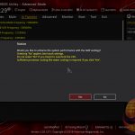
There is a pin on the board that you can switch depending on whether you want better performance or use normal safe settings. At first boot, Asus boards gives you 2 options (F1 & F3). F1 is Normal Settings & F3 is what you want for Overclocking (unlocks the Power Limits automatically). So i t asks you when you start the BIOS for the first time (or after resetting CMOS). Thats the 1st thing you should do. Then you can set AI OC Tuner to Manual (sometimes XMP profile can cause instability if you aim for high RAM OC — sometimes it interferes and hinders the OC, so disabling it is something to keep in mind. I always use Manual when RAM OC).
The other two options are 2 XMP profiles . XMP1 loads only the first few timings and leaves the rest to the Motherboard. XMP2 loads the full XMP profile without the help of the board. Sometimes except for frequency & timings, XMP can change BCLK frequency &/or MCE (MultiCore Enhancement) . That depends on the motherboard.
The next option is BCLK Frequency . Its one of the most important & fundamental options in the System. BCLK is the internal system clock. It affects the CPU frequency but also affects the clock speed of other parts in the System. In CometLake (10gen) Intel decoupled the DMI (Direct Media Interface — similar to PCIe. Its link b/w the Chipset & CPU) from the Base Clock to ensure flexibility & potentially better stability when OC. It can be useful but not all boards have this option in their UEFI (so if you have only BCLK on 10gen & up it probably affects DMI as well). So increasing BCLK helps with Internet Adapters (RAM & DMI) & GPUs (PCIe) in that sense (potentially better Hit-Reg). U essentially OC PCIe & RAM along with the CPU that way. It used to even affect the Sata Hard Disks at some point (fun fact: Intel had overclockable SSDs but decided not to release them at the last moment). So when increasing BCLK you should adjust the RAM frequency for stability reasons (or you can aim for max RAM OC ). CPU Multiplayer affects only the CPU clock speed while BCLK speeds up almost the whole system. Intel is gradually decoupling BCLK from the other components for the last few generations. Some boards have external Clock Gen which improves the BCLK OC. If you have non-K CPU you can OC it that way if the board have external Clock Gen .
BCLK Spread Spectrum: It reduces electromagnetic interference. Disable to achieve higher clock speeds when overclocking.
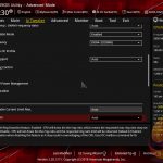
ASUS Multicore Enhancements behaves slightly differently in different boards but in general it does one thing. Sets all CPU cores to the highest Turbo Boost speed. Its essentially a ‘dumb’ overclocking. You should set it to Enable to Remove All Power Limits.
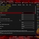
CPU SVID Support should be disabled if you aim for High OC (usually manual voltage). It disables Adaptive Voltage Mode or AI OC . So you need it enabled if use Adaptive/Offset voltage modes. CPU VID sends requests to the board what voltage is needed for the current load & frequency. And SVID Behavior helps you adjust these voltage requests based on the options which represent different scenarios.
SVID Behavior — Auto , Typical Scenario , Trained, Best Case Scenario. It’s used for AI Overclock. It adjusts its behavior based on what option you choose.
AVX Ratio should be 0 for gaming. 1 lowers the CPU Frequency with -100mhz, 2 with -200mhz etc. These days the games use AVX so there are scenarios that you can set it to 1 if you are not stable. Let’s say you have games with & without AVX but that’s your max OC & you crash in the AVX game. Its easier to set 1 instead of using OC software or going in BIOS to change CPU Ratio or BIOS profiles every time you play . That way you can have normal OC for Desktop use & non-AVX games and -100mhz lower clock on AVX ones. There is a possibility in some situations AVX instruction of 1 for ex. to be just as fast as 100mhz higher CPU Frequency (or faster) .
Ring Down -Disabled. That lowers the CPU Cache speed depending on your temps & voltage use.
Max CPU Cache Ratio — Also called Ring or Uncore. The highest stable frequency. You dont really need to set Min CPU Cache Ratio if you want more traditional OC (Multiplayer & Voltage + disable all C-States. No variable voltage like Offset or Adaptive Mode).
PS: CPU Cache or Ring — Its the same voltage: The Ring Bus is the Internal CPU Bus that connects the different Cores, the main highway (so to speak) that connects the whole chip. The other is the cache frequency. Ideally the Cache Ratio should be the same or -1 lower than the CPU Ratio but usually CPU Core Frequency & CPU Cache Frequency difference is bigger. Some ppl use -300mhz less than the CPU Frequency. Usually the Cache Frequency requires more voltage after a certain threshold. For max Competitive Gaming performance & responsiveness, the cache should be as high as possible while being stable.
Older Intel chips kept CPU Core & CPU Cache Frequency 1:1. Its obvious why intel decoupled them. That allowed higher CPU Frequency (which brings more performance) & can add stability, also allowing lower voltage.
I used my 2500k for 6-7+years on 4.8Ghz (1:1 ) on 1.425v. 4.9Ghz 1.495v was also 100% game stable with no degradation (I even played on 5Ghz, but unstable on Air. 5.1 was 97C).
Addressing misconception/misinformation:
So if someone tells you that 1.4-1.45v is too high he doesn’t speak from experience. Google Search is not experience. Intel’s recommendation for a Maximum 24/7 ( every day ) CPU voltage (for 9th & 10th Gen) is 1.520v. (& that IMO is a conservative assessment because they have to take into account the worse chips. The same principle as the Motherboard vendors Auto voltage option in BIOS applies too high voltage for the frequency). These Chips ( 9th & 10th Gen ) are built more robust & can take slightly higher voltages than the previous Intel series. Although I will be careful with 8gen or lower & won’t go above 1.45-1.5v (under load) for daily use (u still can play games on 1.5-1.55v for 2-4 hours as long as temps are good (below 70-80C) but you go into the danger zone (depends on board, cooling & chip quality). Keep the CPU Fans on 80% or 100% when gaming . There are bad/faulty chips that can be damaged so you just have to watch your stats & values for such signs before attempting high OC (I know that’s easier said than done). You have to be an experienced user in this case.
So to recap: Keep your temps below 75-80C , CPU Fans preferably on 100% when gaming (especially on Air Coolers) . Gaming on 1.5+v for a few hours is not a problem if you follow these recommendations. With that said you should be careful when dealing with high voltages. Especially above 6 cores. Skylake architecture (6-10Gen) was meant to be 6 cores max so its easier to fry a chip. Well, the chance is the board to die first is higher.
Extreme Overvoltage is for extreme OC. It will allow higher voltage limits. So you dont really need it enabled if you are on water on air cooling.
BCLK Aware Adaptive Voltage — Disabled for traditional OC (meaning Mltiplayer & Voltage + disable all C-States — No variable voltage like Offset or Adaptive Mode etc.).
CPU Core/Cache Voltage — Auto, Manual, Offset, Adaptive Modes . Most ppl use Manual. Usually people use Maunal at first when want to find the max OC voltage. After you find the max voltage you can switch to Offset if you want, it has many benefits but Manual is more stable on aggressive OC. I set my BIOS in a way that I can switch b/w Balanced mode when on Desktop & High-Performance mode when play games .
Thermal Velocity Boost :
TVB Voltage Optimizations is a useful option. Enable in most cases, disable on Max OC & your temps often exceeds 70C. Optimizes the voltage based on CPU temps. It lowers the voltage when you have thermal headroom.
V-Max Stress will lower the frequency if the voltage is too high & the CPU reaches a certain temp. its explained well in the Bios.
Overclocking TVB : Has several options. Can add extra +100 or 200mhz when the CPU temp is below 70C. Works for Manual but it works better with Adaptive OC. Auto is also a not bad option. You can disable it too. You can disable these options but leave TVB Voltage Optimizations enabled in most cases (unless you have good voltage & temps or it stabilizes the OC). Enabled gives you extra options to lower the frequency with 100mhz if the temp goes above a certain threshold. There are 2 temp options which means u can potentially lower the CPU Frequency with 200mhz if the CPU temp exceeds both temp values you set.
CPU Core Voltage Override:
When setting CPU voltage keep in mind your LoadLineCalibration Level. On some Levels the voltage will increase, on others will decrease based n the load.
For reference. These are just for a general orientation: 5Ghz is around 1.15-1.2-1.3v/ 5.1ghz: around 1.250-1.3-1.35v/ 5.2Ghz: around 1.30-1.4v / 5.3Ghz: around 1.4-1.5+v (Cache takes more voltage than Core Frequency after certain threshold so also depends on that too. Lower Core Frequency could be stable at higher Cache Frequency & the opposite). If your 5ghz OC is stable at 1.2v or lower under load you have a very good chip. My 7600k at 5Ghz uses 1.25v & its pretty good Overclocker (5.3Ghz on 1.39v). These are relevant for most «Core I» Chips, especially for Skylake & newer. Intel 10 & 11 Gen can endure higher voltages than previous CPUs, 11Gen in particular. Alder Lake is different architecture, it should use lower voltages but the heat is on a very small area so its hard to cool. I dont have experience with 10nm yet since its still new so thats as far as I will comment on this. I can also say that by disabling the E-Cores you can increase the P-Core Cache Frequency higher.
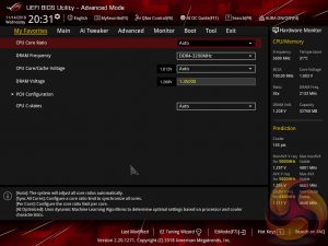
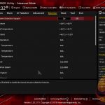
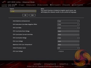
I think here is a good place to talk about the Info area on the right ( Hardware Monitor ). Based on your CPU VID it calculates your CPU on the different frequencies. It can be surprisingly accurate up to a certain voltage. Not always, especially when go for higher OC. You can use it as a general guide. The SP number shows yur CPU «quality» so to speak. Again, its based on the CPU VID, its not set in stone but its a good indicator for moderate OC. For some CPUs can be accurate for others not so much. That’s why you can use the Optimism Scale in AI Features section to adjust it. 76 is not bad but not good too. above 80 are the good chips. Keep in mind that it calculates only the Core Frequency voltage. You can see the Cache has separate predictions. More expensive boards have CPU & Cache separately. Its a good option to unlock with GRUB .
CPU VCCIO & VCCSA (CPU System Agent) voltages: Usually I keep CPU VCCSA slightly higher or the same as VCCIO , that’s not a rule but try to keep similar voltages. Actually depends on Core/Cache/RAM frequencies. If u have a lower CPU Core OC u can keep a lower VCCSA voltage. Since Intel 9th gen the CPUs became more power restricted so many times you can have better OC with lower voltage. That applies to most voltages. A sweet spot.
For up to 8th Gen max recommended daily voltages for both is 1.25-1.3v (higher gets in the dangerous territory). 9th & 10th Gen are more robust and can be set to a slightly higher voltage (if u have a good board & can cool it) but for 24/7 I wouldn’t go above 1.35-1.38v. 11gen even can be set to 1.45-1.5v with good board & cooling, above 1.4 is still potentially dangerous. They can improve stability when OC. VCCIO helps with cache & RAM OC. They both do but it has a bigger impact. Helps more for CPU OC. Intel separated the VCCSA into 2 Voltages since 11Gen. You need to tweak only one of them & leave the other to basically Default.
DRAM Voltage : Highest daily voltage according to Intel is 1.65v but its recommended to stay below 1.6v because of instability problems & degradation. My RAM OC is 1.52-1.54, depending on the timings. When OC the RAM I recommend setting a higher DRAM voltage to ensure the voltage is not a problem & will boot. Find your max OC, then lower & fine-tune it. Some boards have a special option to boot at higher voltage & lower it when Windows loads, some dont.
PLL Termination Voltage- Auto. Can be lowered or increased a bit but better dont touch it.
PCH Core Voltage is the chipset voltage. Set it a bit higher or lower or leave Auto. I might add or remove 0.010v (1.06000v or 1.04000v).
DIGI+ VRM Options:
Some guides completely skip these options, its obvious some ppl dont know what to do with them. Thats why burn CPUs.
CPU Current Capability : MAX (170% in this case). It doesnt mean you will use that much. Its just a power limit, it doesn add more.
Power Duty Control : For more serious OC you can leave it on Extreme if temps allow it . T.Probe is the VRM sensor in this case. ASUS also give you an additional T.Probe sensor you can attach to the board and can put with wherever you want to test the temps. You can use it to watch VRM, Chipset or GPU VRM, Case Air Temp etc.,its a useful Enthusiast feature. So both options are balancing the VRM. T.Probe is balancing based on the VRM Temps & Extreme balance is based on the current (every Phase individually).
Power Phase Control : You eighter can leave it on Auto or Standard (how many VRM Phases are used depends on the CPU) but Standard is for normal use or V/F Curve OC, or if you want a higher OC set to Extreme (it fully utilizes the VRM-full Phase Mode). You can use both Power Options ( Duty & Phase) on Extreme 24/7 if your VRM temps are good. My VRM temps barely get 40-45C on Heavy OC , around 55C in the Summer so I use Extreme.
Synch ACDC LoadLine With VRM Loadline : This can help with V/F Curve OC & Adaptive /Offline Mode. I advise to not enable that unless you know what its for and how it works. Can add stability. But I think that Synch could have a negative effect to ensure stability.
Boot Voltages are the voltage that the PC will start. When Windows starts loading it goes back to normal. You need to know what you really doing to use them. I mentioned it before. It can help to boot with certain OC & use lower voltage after that. Some settings need slightly higher voltage on Boot to be stable. So thats what these options are for.
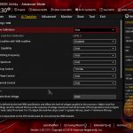
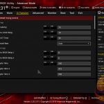
Internal CPU Power Management (AI Tweaker):
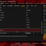
Max CPU Core Temperature : Set to Max temp if you have a good CPU Cooler. You see the screenshot above.
You can copy the screenshot above without the Package Power Time Window option (I would leave it on Auto when OC unless u have a reason). On all slots just type 9999999999 and hit enter. It will auto-set to Max Power Limit (PL) value. This will increase your power usage a lot, you have to keep that in mind. But will run faster.
CPU Core/Cache Current LimitMax : Current max Limit. The CPU wont use that much power. Its basically make it unrestricted.
Long Duration Package Power Limit : (PL2-241W by default ) The Max power is allowed to use when the CPU is in Turbo Boost. You can increase the max power usage from here when OC.
Short Duration Package Power Limit : (PL1-125W by default) Base frequency power usage.
Package Power Time Window : Default Boost time window is 56sec in PL2. When CPU Boosts it increases the power usage . After that time it lowers back to Base Frequency. Thats stock CPU behavior.
IA AC/DC LoadLine : Thats the Voltage Loadline Calibration. It sends data about the VRM design, quality & other characteristics so the CPU can better adjust the vdroop (when the voltage fluctuates — idle/load). Leave it on Auto if your voltage is Manual when OC. This is for a different kind of OC with V/F Point Offset . With the latest Intel CPUs its the better way for the overall highest, well-rounded OC.
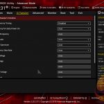
RealTime Memory Timing : is if you want to adjust RAM timings with a program in Windows.
FCLK Frequency on max (1Ghz). Directly affects RAM Speed stability & performance. It can improve communication b/w CPU Cores, Cache, Memory Controller ect. So it can affect RAM OC. Lowering it can add stability to RAM &/or CPU Cache. You can increase it at the end of the RAM OC after you find your best stable RAM Speed & Timings. To get a better perspective on Ryzen CPUs it controls the Infinity Fabric but we’re talking about Intel now. If your RAM OC is unstable, setting FCLK to 800mhz or even 400mhz can help with stability but at the cost of some performance & responsiveness.
DRAM VTT Voltage is always half of the DRAM Voltage. It does that automatically. Sometimes slightly lower than half DRAM settings can have a positive effect on the RAM stability when OC.
PVD Ratio Threshold : This is recommended to set lower if you do high BCLK OC. The default divider is 15 so lower than that. That can add stability when OC BCLK.
The rest of the options can be left on Auto. They can be more needed in Extreme OC but still have an effect on high OC. You can choose to set PLL options on the lowest voltage to save some power. Usually its fine. The lowest should be 0.900v on most. Sometimes the opposite works. To set it slightly higher. Dont go above 1.1-1.2v on PLL Options. CPU StandBy Voltage can be increased to help stability. Im not sure if helps with V/F Curve OC or in general.
Package Temperature Threshold : From here you can limit the CPU Temp. If you use AI OC for ex.
Optimism Scale . The motherboard tries to predict the voltage on certain OC based on the CPU VID voltage. You can feel how much voltage your CPU is using and if its better to increase to higher than 100%. You can have it on 120% for ex. & that way it will predict your voltages better. They test lots of chips & can somewhat predict & have some idea what voltage you should have on that frequency. Its not 100% accurate but its a good feature to point some people in the general direction. Also helps you visualize.
If you use Auto AI OC you can set RegulateTemperature Threshold to 75-85C if you use AI OC. The others are pretty straightforward.
Hardware Prefetcher : This stores data & instructions that can repeat to the L2 CPU Cache (instead of deleting it or copying from the RAM). Its much faster, reduces latency.
Adjacent Cache Line Prefetch : When the CPU receives data from the cache, it can also prefetch the next 64-byte cache line because there’s a high probability the CPU requires the next cache line as well. You should keep both Prefetcher options enabled. Especially on old CPUs. Could be Disabled for Servers.
Sometimes Disabling Prefetch options can add some stability to CPU Cache OC. These days both Prefetchers can be disabled but they still help in certain repetitive workloads. In the past they had a positive effect in Gaming. My 2500k ran with around -30FPS less with them disabled in BF3.
Intel Virtualization Technology — Disable for Gaming. Its for Virtual Machines & Security.
Hyperthreading — Should be Enabled in 99% of the time including games. No reason to Disable it on Intel CPUs. Ryzen SMT is a different thing. Telling people to disable Hyperthreading on Intel CPUs is Stupid unless it’s a light game that utilizes fewer threads than the CPU has . Or you are a » Competitive Latency Monitor player» LOL 😀 That program is not a gaming benchmark and doesn’t show the real scope of that feature. Ryzen SMT is still not mature enough (especially Zen 1 & 2 ) & can be disabled in some situations but this depends on every game individually , it’s not a rule.
Per-Core Hyperthreading : U can disable Logical Cores individually. That can help with weak Cores for ex. Disabling the HT can help with OC stability. Thats viable if you have more cores than the Game/Benchmark uses and/or it gives you a higher frequency that helps in the game more than 1-2 Logical Cores. More useful in Competitive XOC. I believe that feature was introduced in Intel 10 Gen.
MonitorMWait : Its an instruction that hints the CPU to enter an optimized state (C-State). It has two main usages: address-range monitoring & advanced power management. The Thermal Monitor option also has to be enabled to work. It also disables the C-states Option in my board so safe to say you need these two enabled if use C-States. If you disable all C-States you can disable them.
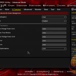
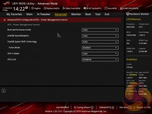
CPU Power Management Control :
I will show two ways of setting these options here.
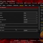
Intel Speed Step- Auto
TurboMode- Always Enabled.
C-States — Enabled. All C-States Disabled with exception of C0/C1
Thermal Monitor -Enabled.
DualTauBoost-Disabled. This should give you longer TurboBoost (Useful on Non K CPUs)
CPU VID Enabled (this could improve CPU OC if disabled)
TVB Voltage Optimizations also could be Enabled (Can be both)
Intel Speed Step- Disable
TurboMode- Always Enabled.
C-States — Disable. All C-States Disabled .
Thermal Monitor -Disabled.
VT-d : This is Directed I/O Virtualization Technology. Without this, features like Direct Cache Access & NetDMA wont work. Its useful in Virtual Environments.
Memory Remap — Allows you to use previously unusable RAM portion so you can use all of your RAM.
Somewhere in these options is GPU Clock Gating . Its a power-saving feature. Disable it.
Primary Display for most people to Auto or PEG. PEG is your Dedicated GPU. Auto can fix some compatibility issues, especially when tweaking. You can also choose to disable the integrated iGPU or use it as 2nd monitor . Ideal for power-saving. Windows have options in Settings Panel to choose it for multimedia like video/audio player, Internet Browser or something else. It will boost that way the performance on normal everyday Desktop use. Especially useful in laptops & some programs. Enabled iGPU can lower your max OC so if you aim for that you should Disable it. If you want to use iGPU as well, you can use Auto settings here & enable iGPU Multi-Monitor .
PEG Port Configuration : PCIe Slots (PCIEx16_1 Link Speed) — Gen3/4 (highest) only on the populated slot-upper slot/#1 slot. This is the link with your Discrete Video Card. You can fix crashes or Dx Errors on high/unstable GPU OC by setting it to Auto so the system can adjust on the fly. It will stay Gen 3 or Gen 4 when on Auto. U can check that with GPU-Z.
So there are 2 separate options that you can choose the link generation. GPU ( PEG ) & Chipset ( PCH ). Since 10Gen DMI (Direct Memory Interface. Its the link b/w CPU & Chipset. Important. Can even speed up networking #Blink/N udge xD ) is decoupled from the Base Clock & you can adjust it separately from the base clock, which gives you more flexibility & potential OC & performance gains. Unfortunately there is no such option on this motherboard.
PCH Storage Configuration : Just copy the settings and here I disable the Sata slots that are not in use- its not a big thing, u dont need to do it if you dont care. U can also leave S.M.A.R.T. Self Test can alarm you if your disk is about to fail so you can have time to make a backup. Up to you. If you have only NVMe & dont have SATA disk you can disable the SATA Controller . From here you can enable RAID support. Hot Plug means you can plug in/out the disk (similar to USB drives) without the risk of losing the data. A good example is if you have an external disk.
Aggressive LPM Support is a power-saving feature. I think it means Low Power Management or similar.
PTT (Platform Trust Technology) : You can On/Off the TPM (Trusted Platform Module). So its a security feature. If you install Windows 11 that is recommended to be enabled. Ofc. there are ways to Install Win11 without it. Its related to TPM 2.0. Im not gonna talk about the compatibility options here.
Above 4G Decoding : That’s the RAM reserved for the CPU ( for a period of time) when working with video memory. It allows you to work with GPU vRAM. So it increases the RAM reserved for the CPU when accessing the video memory . It has to be Enabled in order to Enable Re-Size Bar Support (u need to have at least RTX3000 or Rx6000 to work). AMD named it SAM (Smart Access Memory) . Thats a PCIe feature & its nothing new. I think its important to know that enabling Re-Size Bar can increase or lower FPS but usually its normal to have less FPS with better input lag. Unfortunately, I haven’t seen such test, only generic benchmarks presenting FPS numbers that don’t show the whole picture. So with this feature, I think you can have a slightly lower FPS but better latency. Thats the usual trade-off. Dis able Sr-IOV Support . Its a virtual option. If you have a Server or work with Virtual Machines you will know what to do with it. Not for Gaming.
Legacy USB Support — Enable. XHCI Hand-Off is a workaround in case the OS doesnt have native support. XHCI is supported by Windows 10/11 so the intent is that u can disable it. I imagine XHCI On could improve the driver’s behavior. I haven’t tested it though.
Mass Storage Devices is your USB Flash Drive so leave SanDisk on Auto.
USB Single Port Control : The same as with the Sata links. You can disable USB ports that you dont use. For ex. I dont use USB Type C. No need to waste energy you might need elsewhere. Could help with Max CPU OC in rare cases (if you disable enough ports, RGB & other power wasters), depends on the board so its not sure that will work, just something u can do. You can leave only the USB ports that u r actually using & disable the rest. This option is useful in troubleshooting. Since we talk about USB I’ll mention that the best USB ports for Mouse & Keyboard are usually the top 2 ports. If you have BiosFlachBack USB Port you can use it for the mouse. In many cases that’s the best route to the CPU.
Onboard Device Configuration : Same thinking here. Disable what you’re not using. U can disable LED & other lights — Stealth Mode. The only useful feature is to change its color when CPU temp gets too high (above certain temp u set).
Be careful how many M.2 You’re using and how many PCIe lanes the CPU & the Chipset have. Some people use less lanes for the GPU & run in PCIEx8 or Gen2 instead of Gen3 exactly because use too many NVME SSDs. That can lead to poor GPU performance. I would leave M.2 options on Auto so they can configure on the fly. Also set PEG option (I showed earlier) on PCIe Gen3 (Gen4 if u have. But if you experiencing «Dx Errors» when gaming you can try setting PEG on Auto ). It usually gets Dx errors when GPU OC is unstable.
Sensors : Same mentality. Disable everything you dont use.
FANs & Pumps have DC & PWM mode. If u r not certain which one is the fan leave it on Auto. PWM is more advanced & can use lower voltage which lowers Fan Speed & Noise.
Fast Pumps & Fast FANs usually use DC (also older ones). They’re usually cheaper because dont have this voltage granularity as PWM. PWM FANs can run slightly faster when set on DC mode (which usually uses higher voltage).
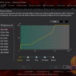
I wont be talking about Monitor Section for now, its has a lot of options but once you get it its the same for every FAN Option. In general its a way to fine-tune your FAN speed above (or below) certain temps. Its for advanced users who want to have 1 setting for all scenarios. Most users use Auto or Manual.
On this BIOS F6 shows you quick FAN settings. I would use this to configure my FANS. Its easier to understand. There are options that Fine-tunes your fans voltage individually for every fan (on the different speeds).
I highly recommend using all fans on 100% when Gaming, OC or use the computer for other intensive workloads. Gaming is not considered an intensive task because of the way it works with load fluctuation. But if you have high Overclock 100% FANs can give you an extra 10-15C over Auto. Adds stability & prevents overheating. Auto cant increase the fans quick enough.
ASUS ROG Strix Z390-E Gaming Motherboard Review
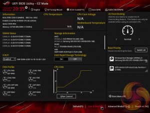
The ASUS UEFI enters straight into the EZ Mode splash screen which has a selection of frequently used settings including XMP profiles, boot device order and fan speeds. Pressing F7 takes the user into the advanced section of the UEFI but there are some additional tools that can be accessed from the splash screen such as Q-Fan Control, EZ System Tuning and AI Overclocking.
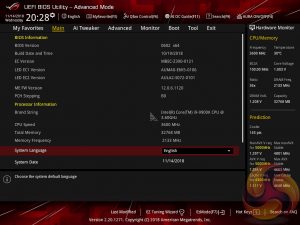
The first tab is MyFavorites which stores the most frequently accessed UEFI settings. The next tab, Main, contains detailed processor and BIOS version information.
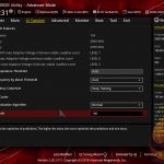
AI Tweaker is the UEFI tab which contains the vast majority of performance tuning settings pertaining to the CPU and DRAM. From here you can set XMP profiles, overclock the CPU, set all the various voltages and voltage operation modes, change the Load Line Calibration (LLC) and considerably more.
LLC has 8 levels, using a 0-based index, with 0 being the least aggressive and 7 the most. The voltage modes include manual, adaptive and offset. Unlike MSI, ASUS does not offer combined voltage modes such as override + offset.
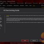
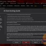
ASUS has implemented a new “AI” overclocking feature which can be enabled through the “AI OC Guide” window (F11). This has an “optimism scale” associated with it which will determine how adventurous the target overclock will be, there’s also a cooler calibration test which effectively tests “how good” your CPU cooler is before attempting higher voltages. The scale ranges from 50, least optimistic, to 150, most optimistic, with 100 being the default.
There’s also a feature called “SVID behaviour” which affects the level of input voltage the CPU will use at a given voltage. There’s an option to run this as “best-case”, “typical”, “worst case” or “Intel’s Fail Safe” scenarios but effectively what it means is that, in that order, power consumption goes from lowest to highest. A best-case scenario assumes a high-quality chip that requires less power to operate, and Intel’s fail safe is the opposite.
In practice, manually setting the CPU VCore overrides the SVID behaviour but anyone who just dials in a 50x multiplier for 5GHz and leaves the voltage to auto, would be affected by the SVID behaviour. This is also relevant when using Adaptive and Offset VCore modes since those modes will add or subtract voltage from the VCore based on the SVID set voltage, so a higher or lower the baseline level set by the SVID behaviour will affect the final VCore under load.
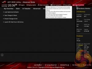
The UEFI provides a clear warning that when enabling XMP there is a choice to opt out of enhanced Turbo functionality and stick to Intel’s default CPU specification, particularly pertinent for Intel’s new i9 9900K which can consume large amounts of power. The same also applies for the memory specification which ASUS claim can be enhanced (XMP I) instead of sticking to the complete XMP profile (XMP II).
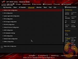
There is a significant selection of performance and compatibility parameters to be found under the Advanced section should the need arise. As well as a number of other peculiar settings related to the functions of onboard devices, LEDs, USB and storage controllers and more.
The Monitor tab will allow you to instruct the UEFI how to handle temperature data from the various sensors as well as what to do with fan speed profiles. For example where a fan speed profile is temperature dependent you can choose which temperature sensor to use. If you purchase the optional ASUS Fan Extension card that can also be configured from within this section.
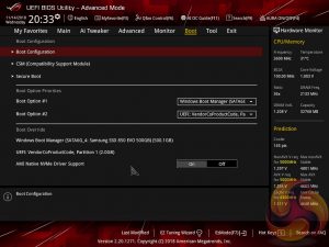
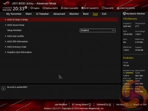
The Boot tab is as expected in delivering the key boot options such as secure boot, boot priority and boot compatibility options. Users needing to update the UEFI (via the EZ Flash Utility), save, import or export BIOS settings, or secure erase a storage drive should refer to the Tool tab.
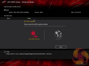
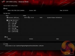
The EZ Flash utility is very simple to use and allows the UEFI to be updated from either a local disk or the internet over the Intel I219V Gigabit Ethernet adapter.


The ASUS AI Overclocking replaces the previous EZ Tuning Wizard for automated overclocking, and also takes its F11 hotkey in the UEFI environment. This is an improved version of EZ Tuning Wizard that takes into account thermal data, i.e. the effectiveness of the CPU cooler, when overclocking.
ASUS claims they have developed a “proprietary algorithm” which tests the quality of the CPU and mixes that with the capability of the CPU cooler to give a better result. When we enabled this using “100” optimism after calibrating our CPU cooler we got a 166 points score for the CPU cooler, with a “4.8GHz” turbo mode for non-AVX workloads and 4.6GHz with AVX and 4.65GHz cache. The light load result was 5GHz while the heavy load result was 4.8GHz, all using 1.204
1.257v (non-AVX/AVX) for the CPU and 1.1v for the Cache.
Changing optimism to the max, 150, scored us a result of 5.5GHz non-AVX, 5.4GHz AVX, 5.4GHz cache and 5.5/5.5 GHz light/heavy with 1.436
1.438v (non-AVX/AVX) and 1.041v (cache). (un)surprisingly enough, this didn’t boot!
In most cases the result will be “improved” over the peculiar results EZ Tuning Wizard used to deliver – with painfully high voltages for relatively low clocks – but taking the time to tune the overclock yourself based on some research for your circumstances would still be the better way.
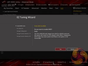
The EZ Tuning Wizard has been relegated to just being for RAID setup and configuration, like on the H370 platform where overclocking isn’t supported. This used to be the “automated overclocking” utility until ASUS replaced it with the “AI Overclocking” guide.
The search function allows a text string to be searched against all the UEFI parameters. It isn’t a smart search so doesn’t have an auto-fill function and will not find similar items to your search string i.e. M.2 when M2 is searched.
ASUS has some basic AURA RGB controls from within the BIOS that are variations of “on” and “off”. There is companion AURA RGB software to go with the motherboard that is used for the colour and lighting customisations.
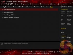
The Exit tab is fairly self-explanatory and helpfully provides a summary of changes upon exit.